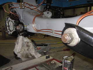
And because I fitted the felt seals at the rear- and front end of the crankshaft over 6 months ago , they were leaking pretty bad, especially the rear one...
Felt seals only seal when they're soaked in oil, so hopefully the leaking will stop after running the engine for a while.
First I had to tighten the cylinder head bolts for the last time to a torque of 92 Nm. Before I removed the rocker shaft and arms I checked the valve clearances. 3 were to tight, 2 too loose..
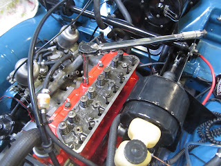 |
| Tighten the cylinder head bolts of the Volvo B20B |
 |
| Volvo B20B rocker shaft and push rods |
When you put back the rocker shaft, make sure everything is in line; push rods right under the arms etc. Don't forget to adjust the valve clearances again.
 |
| Setting the valve clearances with the pulley mark on 0 degrees |
Now you can set valves 4, 6, 7 and 8 (the first valve is in front and no 8 at the back of the engine). Turn the pulley 360 degrees so the "0" is again in line with the mark and you can adjust valve 1, 2, 3 and 5.
The basic settings for the B20B engine before you try to start it:
- Spark plugs gap: 0.7 - 0.8 mm
- Contact breaker gap: 0.4 - 0.5 mm
- Valve clearance inlet and outlet: 0.5 - 0.55 mm
- Float level SU carburettors: 4.8 mm (see pics)
 |
| Float SU carburettor Volvo 122S |
 |
| Maximum fuel amount in the float chambers when the float level is correct |
Basic setting for the SU-HS6 carburettors:
 |
| Intermediate shaft and levers Volvo 122S |
 |
| 0.5 mm feeler gauge between the bracket and it's stop ("A") at the intermediate shaft and lever |
- Place a 0.5 mm feeler gauge between the bracket and it's stop ("A") at the intermediate shaft and levers (see pics above) and release the nuts 3 and 10, push the pins down so that they make contact with the lower tooth of the levers of the throttle spindles. Don't push so hard that the levers start to move! Now tighten the nuts 3 and 10.
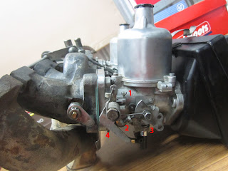 |
| Tuning the SU-HS6 carbs |
- Turn the throttle stop screws (1) out until they just lightly touch the levers and then turn them in 1.5 turn.To check when the screws start to touch the levers I always put a piece of paper between the screw en lever. Keep moving the paper until you feel resistance, now that's the correct point
- Screw in the jets (3) until they are flush with the bridge, (the jet just touches the air valve). I checked this first just by looking and if it looks OK by lifting the air valve and let it fall while holding my finger at the bottom of the black plastic part. This way you can feel if the air valve hits the jet or not. Then it's a matter of fine tuning
 |
| Jet flush with bridge SU-HS6 carburettor |
- Now screw out the jets 15 hex flats (2.5 turns) -I put a dot with a marker on the hex flat in front when the jet just touches the air valve, which helps while counting. You'll see that you probably have to adjust the jets a couple of times before you get them right.
- Fill the damping cylinders with special ATF oil (type A), 6- 6,5 mm from the top.
Always start with the ignition and valves before tuning the carburetors.
Setting the Dwell Angle
When the engine is running you can measure the Dwell Angle, this is a more accurate way of measuring the gap between the breaker points which should be 0.4 - 0.5 mm. The Dwell Angle for the B20B engine should be between 59 - 65 degrees. To measure the Dwell Angle, advance timing settings and the RPM you need a special multi meter (see pic).
 |
| Optilux Timing/dwell/rpm multi meter |
Because I always like to know why I have to tune something and how it works first some theory about setting the dwell angle: The distributor shaft has to ignite four sparks in one turn (360 degrees). So we have 90 degrees for each spark. The spark is made by the ignition coil. This coil needs a certain amount of time to build up the power for the spark. This is only possible when the breaker points are closed. A dwell angle of, let's say 60 degrees means that the breaker point should be closed 60/90 part of the time to build up enough power for a strong spark. The bigger the contact breaker gap the lower the dwell angle!! If the dwell angle is to high, the breaker points will wear and get pitted very fast. If the dwell angle is to low the spark can get to weak, especially when revving the engine.
 |
| Bosch Distributor JFUR 4 - Volvo 122S B20B |
Next thing to tune is the ignition timing.
In order to get max power on the pistons you need max pressure of the explosion when the Piston is in TDC (Top Dead Centre), but because the fuel/air mixture need a certain time to burn and thus generate max pressure it has to be light (sparked) before the piston is in TDC. So we need to advance the ignition.
There are several things that contribute to the advance settings:
- Initial (base) Advance Timing
On the pulley you can see marks (the same pulley we used for setting the valve clearances) and when the engine is running at idle speed (Volvo B20B around 800 rpm) you can look at it with the stroboscope light and read the timing.Disconnect the vacuum hose and plug the hole before you start. In order to change the timing loosen the bolt that holds the distributor a bit and carefully turn the distributor while the engine is running at 800 rpm. Turn to the left will increase the advance, turn to the right will decrease the advance setting. For the Volvo B20B the base advance should be 10 degrees.
- Mechanical (Centrifugal) Advance Timing
When increasing engine speed (rpm) it needs more advance timing to keep up with the piston speed because the time the burning gasses need to reach optimum pressure to push the piston down when it is in TDC stays almost the same. The mechanical timing advance is caused by a mechanism inside the distributor. The distributor in the Volvo B20B has a total (max) mechanical advance of 13.5 degrees (+/- 1 degree). And because the distributor turns half the speed of the crankshaft you have to multiply it by 2 to calculate the real advance.
It's important to know that the Total Advance Timing (Initial + 2x Mechanical) has a max of around 38 degrees. If you set it higher the engine can start to pink (gas detonates too early caused by high pressure/heat) which can cause severe damage! It's a "metallic pinging" sound.
- Vacuum Advance Timing
A lean mixture needs more time burn. So when the engine is idling or your driving at a constant speed on the highway the engine needs a bit more advance then normal. This is when the vacuum advance kicks in. Vacuum in the carburettors is at it's highest point when idling or travelling at a constant speed with low rpm.
Normally, yes... But the Volvo B20B engine has a distributor with a vacuum system that retards the timing.. I still have to find out why and how.
 |
| Specifications Bosch JFUR 4 Distributor |
Keep in mind that the specifications given by Volvo are based on an original/unmodified engine and when the fuel used to be 100 oct or more. When the octane in the fuel is lower you need a lower initial advance timing. I think around 8 with 95. But.. because my engine has a sporty K-camshaft it needs an higher degree of advange than normal (because the valves open earlier than normal). I couldn't find the corresponding Settings for the K-camshaft but for now I'll set it around 12 degrees. If you want maximum power from your engine set it as close to pinking as possible. So when I take it for a ride when it's finished and it's not pinking maybe I'll give it 1 or 2 degrees more Advance timing..
Fine tuning the SU-HS6 carbs.
I did the settings without a CO-meter. According to the manuals Temperature is an important factor when making the settings;
- Ideally the outside/shed temp should be between 15-25C
- The settings should be made within 1-3 minutes after the thermostat has opened!
So start the engine and run it warm at around 1500 rpm until the thermostat opens (the top hose suddenly becomes warm) and then adjust the throttle stop screws (1) until the engine speed is 800 rpm. Turn both screws equally!!
Now turn the jet nut (3) of the rear carburetor until max idling speed is obtained and then turn them inwards (leaner mixture) until the rpm starts to drop. This is the right setting. To check this, push the lifting pin, the rpm should drop 150-250 rpm. I had to turn the jet adjusting screws almost 3 hex inwards counted from the "zero"setting to get the setting right.
Re-adjust the idling speed with the throttle stop screws to 800 rpm.
I had a couple of "problems" before the B20B was tuned. First problem was flooding caused by a wrong float level (ca.4.6 mm) at one of the floats. I adjusted both float levels to approximately 5.2 mm, because I didn't want any more fuel from the float chambers leaking on the hot exhaust ("better safe than sorry"). The flooding stopped.. but so did the engine after a minute or 2. Hmm, what's wrong this time.. I checked the float chambers and they were almost empty!! Apparently there are really narrow margins around the 4.8 mm float level.
The next issue was a uneven idling. Normally this is caused by a vacuum leak. Well I found two.. The old hose from the brake booster was ripped (hard to see because it was the underside) and the other one was the preheating chamber in the inlet manifold caused by 2 "loose" bolts (see pic above).
I also need a new air filter because the old one is so dirty it almost suffocates the engine.
Update 05-04-2014: check for more tuning also http://volvo-122s.blogspot.com.au/2014/03/volvo-122s-b20b-engine-more-tuning.html
O.... and the felt seals luckily stopped leaking after a while, All good
Volvo B20B engine after some tuning
I had a couple of "problems" before the B20B was tuned. First problem was flooding caused by a wrong float level (ca.4.6 mm) at one of the floats. I adjusted both float levels to approximately 5.2 mm, because I didn't want any more fuel from the float chambers leaking on the hot exhaust ("better safe than sorry"). The flooding stopped.. but so did the engine after a minute or 2. Hmm, what's wrong this time.. I checked the float chambers and they were almost empty!! Apparently there are really narrow margins around the 4.8 mm float level.
 |
| Almost empty float chambers caused by a wrong float level |
The next issue was a uneven idling. Normally this is caused by a vacuum leak. Well I found two.. The old hose from the brake booster was ripped (hard to see because it was the underside) and the other one was the preheating chamber in the inlet manifold caused by 2 "loose" bolts (see pic above).
 |
| Ripped vacuum hose from inlet manifold to the Ate brake booster |
Update 05-04-2014: check for more tuning also http://volvo-122s.blogspot.com.au/2014/03/volvo-122s-b20b-engine-more-tuning.html
O.... and the felt seals luckily stopped leaking after a while, All good
Volvo B20B engine after some tuning


