Oct 16, 2013

Bleeding the brakes

It has been a while since I fitted the new brake lines. After fixing the rear drum brakes I could finally fill the braking system with fresh DOT4 brake fluid. When fitting new brake lines you tighten them ca. 1/8 -1/4 turn after feeling resistance. But you'll never know if it's tight enough until you fill the system with new brake fluid.

Brake line connections

Normally 200-300 cc brake fluid is enough to fill an average car brake system. But because this is about filling an empty system you also have to get rid of the air by bleeding and I needed around 600-800 cc to get the job done.

So filled the system through the brake fluid reservoir and started checking all the brake line connections. I counted 32 connections on this duel brake system. 2 of them were leaking right away but with a 1/8 extra turn the leaking stopped.

I jacked the car a bit higher at the rear hoping that most of the air in the system would go there.

The Volvo 122S with the dual line system has 8 bleed valves; each front caliper has 3 valves and each rear wheel one (just above where the brake line goes into the brake/wheel cylinder).

3 bleed valves front brake calipers Volvo 122S
3 bleed valves (covered with rubber caps) for the front brake calipers

The brake bleeding sequence for the Volvo 122S dual line system:

  1.  Left rear wheel
  2. Left front wheel, upper, inner
  3. Right front wheel, upper, inner
  4. Right rear wheel
  5. Right front wheel, outer
  6. Right front wheel, lower, inner
  7. Left front wheel, outer
  8. Left front wheel, lower, inner
Normally you need 2 people to bleed the brakes; one pumping the brake pedal and the other opening and closing the bleed valves. But with some simple self made tools you can do it alone.

You need two "tools" to make brake bleeding easy.
The first one is a cap with a valve for your brake fluid reservoir and the second one is a clear hose with a small valve at the end hanging in a jar filled with brake fluid. 

Brake bleeding tool
2 Brake bleeding tools

I bought a $4,- dollar spare cap, drilled a hole in it and tapped in an old bike valve tube. I used some Teflon tape an two o-rings to make it air tight. I screwed it on the reservoir and now I could put pressure on the brake system with a simple hand pump. Not to much, 3-4 pumps are enough. 

Brake fluid reservoir cap with "pressure" valve

Modified cap on brake fluid reservoir

When you open a bleed valve you want the air going out, not air going in! So you need a clear plastic tube that fits the bleed valve, push a bicycle tube valve in the other end (top of the valve in the tube!) and let it hang in a glass jar filled with fresh brake fluid. The valve will let the old brake fluid and air going out but prevents air from going in when the pressure in the system isn't high enough.

Brake bleeding tool - bicycle valve in clear tube
bicycle valve in bottom of clear tube

When I put some pressure on the braking system more the half of the connections started sweating, so I fixed this first (1/8 -1/4 turn extra) before bleeding the system. 

The tools did their job and after bleeding all the valves twice I'm pretty sure there's now only brake fluid in the system. Don't forget to check the level in the brake fluid reservoir while bleeding and top up when neccessary. Btw I took all the wheels of which will make the bleeding a lot easier.

Bleeding the dual brake system

While the car was still jacked I tested the brakes by turning the wheels as fast as possible by hand and then hit the brake pedal, all good.

The next test was driving the car on the driveway and hitting the brakes, very exiting .. the driveway was ca 35 m long and with the shed open I had an extra 10 m. The first time I drove really, really slow and hit the brakes, they worked! So this time I took of fast,put in in second gear and with a speed of ca 15 mph I hit the brakes again, it stopped again!

I could also feel the assistance of the brake servo so that one functioned too. Now it was time to check the unions and connections in the brake system again, ^#%#@$ half of them were sweating! Well it wasn't a real problem just some extra work tightening them and bleeding the system one more time just to make sure... 

Oct 13, 2013

Fixing the rear wheel drum brakes

The Volvo 122S  rear wheel brakes are of the drum type. In order to remove the drums you need a special drum brake puller. And because I didn't had this special puller I postponed this job for months. Finally I decided to buy one of those pretty expensive pullers and last weekend the brakes saw daylight after decades of darkness...

Original Volvo 122S drum brake puller

Don't try to use universal pullers because you will certainly damage the brakes.
Instead of most universal pullers this original one has a big bolt with a flat end. Most other pullers have a center point end which can easily damage the drive shaft. I used a special hammer spanner to loosen the drums. After hammering the spanner a couple of times the drum came loose with a big bang.

Volvo 122S rear drum brake

Volvo Drum brake puller with 32mm hammer spanner

Finally the drum came loose

Inside the Volvo Amazon's right drum brake
Inside the right drum brake

 As you can see in the pic above the brake shoes in the right drum were upside down. The lining of the brake shoe at the end should start on top of the shoe. If the shoes are fitted the wrong way round the handbrake won't work correctly.

New Volvo Amazon drum brake shoes
New drum brake shoes

The latest model Volvo 122S has self adjusting drum brakes. Every time you pull the handbrake the brakes will be adjusted. Unfortunately this system isn't very reliable so it's a good idea to check 'm every now and then. They can also be adjusted by hand just by putting a screwdriver into the little hole in the drum and turn the adjuster screw a couple of notches.

After taking all the old parts out I gave the brakes a good clean and took off the sharp edge of the lining before putting in the new brake shoes.

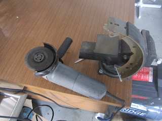
Taking off the sharp edge of the brake lining with a grinder
Grinding off the sharp edge of the brake lining

Shaved lining brake shoe
I also replaced the wheel cylinders and brake hoses, they aren't too expensive and I was pretty sure the old wheel cylinders wound't work after doing nothing for more than 15 years. The flexible hoses can be very tricky because the look good on the outside but after many years they are swelling on the inside en thus are often blocked. Don't forget the copper ring between the brake hose and the brake valve

Old flexible brake lining removed

Fitting the new brake hoses
Fitting the new brake hoses with copper ring

Left drum brake Volvo 122S with new parts
Make sure the big bolts are fully tightened. I used the 32 mm hammer spanner to tighten them.


Right drum brake Volvo 122S with new parts
Drum brake ready for the wheel

Time for fresh brake fluid and bleeding the brakes.

Aug 28, 2013

Flooding SU carburetors

When the B20B engine was idling for a couple of minutes the SU carburettors always began to flood. I played with the floater height, replaced the floater needles, put back in the old ones, took the carbies off..... Nothing really helped. The only result was that I now can rebuild and tune SU HS6 carbies with my eyes closed.

And as the SU HS6 carburettors are mounted just above the exhaust  flooding can be dangerous too!

It must be something else, something outside the carbs....
Well, I fitted a new aftermarket mechanic fuel pump in the car and I've heard that new fuel pumps often gave a higher than desired pressure. And another thing was I fitted a new camshaft with a fresh "eccentric lob" what would cause an even higher pressure (caused by a longer stroke).

Mechanism Mechanic Fuel lift pump

After market Fuel pump Volvo 122S

There are three solutions to solve this; one is to fit an extra or extra thick gasket between the fuel pump and the engine (shorter stroke > less ml fuel/stroke) and number two is to place a Fuel Pressure Regulator (FPR) between the fuel pump and the SU carburetors. Three is to buy an original fuel pump (I'll keep that one in mind if I ever need a new fuel pump..)

A twin SU HS6 carburetor can handle a pressure of ca. 2.5 - 3.0 psi.
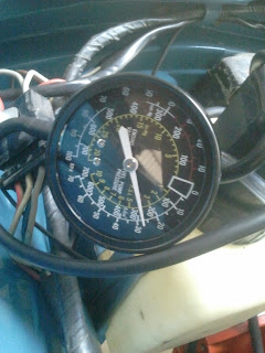
To measure the pressure you need to disconnect the fuel line from the carbies and put the adapter from the gauge in the fuel line. The fuel in float bowls will keep the engine running long enough to measure the pressure. It was 4 psi while the engine was idling!

Measuring the fuel pressure Volvo Amazon
Measuring the fuel pressure
After installing the adjustable Fuel Pressure Regulator I set it on 2.5 psi. No more flooding! As the car is still in the shed I don't know if 2.5 psi is enough while driving it so maybe I've to set it on 3 psi.

Fuel Pressure Regulator / FPR in the Volvo 122S
Fuel Pressure Regulator in the Volvo 122S

 Btw the Fuel pressure gauge can also be used to measure the vacuum of your inlet manifold. This should be around 18-21 with an idling engine (no matter what engine). Of course I couldn't resist this opportunity... All good!

Measuring the inlet manifold vacuum
Measuring the inlet manifold vacuum 

Aug 27, 2013

Radio and new Dashboard for the Volvo

The radio that was in the Volvo 122S since 1970 wasn't working too well. So I decided to put in a nice new one. BTW they call it a Media Player instead of Radio nowadays... whatever...
I did like the looks of the old school radio so I only disconnected it and left it in the metal dashboard.
After some desktop research I found a nice Radio for just under $100,- with Blue tooth and, very important, remote control.  It's a Sony DSX-A50BT (if you wanna know :0)

Now I had to find a good "out of sight" place for the new Radio and speakers. The glove shelf is mounted on the firewall with two screws, and even better the distance between the screws is almost ideal for the new Radio. Now you probably also understand why I needed a radio with remote control...

Radio mounted with brackets in Volvo 122S

I bought 4x 20 cm long metal brackets with holes. The brackets were easy to bent but strong enough to keep the radio and front speakers  in place. The distance between the holes in the brackets was the same as the mounting holes in the radio so that part was easy.

The old antenna was still in good condition but as I didn't want to drill another hole in the fender I found a nice spot under the dash and mounted it with two tie rips.

External Antenna hidden behind dashboard Volvo Amazon
External Antenna hidden behind dashboard Volvo 122S
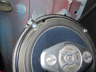
Two 220W 4-way Pioneer speakers were used as front speakers. No particular reason for Pioneers, I just found them new in a box in a Saab 900 wreck (but that's another story).
As I didn't want to drill more holes in the body I took longer top bolts for the bonnet mounting, made the holes in the brackets a bit bigger and bolted them on the inside thread of the longer bonnet bolts.

Speakers mounted on longer bonnet bolts Volvo Amazon
Speakers mounted on longer top bonnet bolts Volvo 122S

Speakers mounted on longer bonnet bolts Volvo 122S
Right speaker mounted with brackets on longer bonnet bolts

Left speaker and Radio hidden under dashboard Volvo Amazon
Left speaker and Radio hidden under dashboard 

 Can you remember the old original dash pad? After more than 40 years in the harsh Australian sun it was cracked, shrunk and totally useless. I tried to repair it but it was too deteriorated. Buying a new original one seemed like trowing money in the well known pit. Then I found a good solution; a polyester replica of the original dash pad. Looks exactly the same as the original and won't crack or shrink in the hot sun.


Old cracked dash pad Volvo 122S
Old dash pad Volvo 122S

Old cracked dash pad Volvo Amazon
Cracked...

Old dashboard Volvo Amazon
....

New polyester dash pad Volvo 122S

It was a bit fiddly to fit the polyester dash pad. You have to drill the holes in the dash pad yourself. This is because not every 122S has the pre-drilled mounting holes in the metal part of the dashboard in the same spots. So it's a lot of measuring (and a bit of bending) but after a couple of hours I was happy with the results.


New polyester dash pad Volvo 122S

New polyester dash pad Volvo 122S
New dashboard Volvo 122S


Jul 28, 2013

Tuning the Volvo B20B engine

With the basic settings right it was possible to start the Volvo B20B engine. But the engine sounded rough while idling and was shaking heavily, mainly caused by the imbalanced SU carbies.

And because I fitted the felt seals at the rear- and front end of the crankshaft over 6 months ago , they were leaking pretty bad, especially the rear one...
Felt seals only seal when they're soaked in oil, so hopefully the leaking will stop after running the engine for a while.

First I had to tighten the cylinder head bolts for the last time to a torque of 92 Nm. Before I removed the rocker shaft and arms I checked the valve clearances. 3 were to tight, 2 too loose..
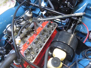
Tighten the cylinder head bolts of the Volvo 122S B20B
Tighten the cylinder head bolts of the Volvo B20B

Volvo B20B rocker shaft and push rods

When you put back the rocker shaft, make sure everything is in line; push rods right under the arms etc. Don't forget to adjust the valve clearances again.

I found an easy and more accurate way to set the valve clearances: Turn the crankshaft pulley CW until the "0" on the pulley is in line with the mark on the cover (taking the spark plugs out before you do this will make it easier to turn the pulley).

Setting the valve clearances Volvo Amazon with the pulley mark on 0 degrees
Setting the valve clearances with the pulley mark on 0 degrees

Now you can set valves 4, 6, 7 and 8 (the first valve is in front and no 8 at the back of the engine). Turn the pulley 360 degrees so the "0" is again in line with the mark and you can adjust valve 1, 2, 3 and 5. 

The basic settings for the B20B engine before you try to start it:
  • Spark plugs gap: 0.7 - 0.8 mm
  • Contact breaker gap: 0.4 - 0.5 mm 
  • Valve clearance inlet and outlet: 0.5 - 0.55 mm
  • Float level SU carburettors: 4.8 mm (see pics)
Using a  4.5 mm thread to measure the float level SU-HS6 carburettors
Using a  4.5 mm thread to measure the float levels, because the float levels should be 4.8 there should be 0.3 mm room between the thread and the float. You can change the level by carfully bending the lever (C) at the hinge pin (E).

Float SU carburettor Volvo 122S

Maximum fuel amount in the float chambers when the float level is correct


Basic setting for the SU-HS6 carburettors:
accelerator Volvo Amazon
Intermediate shaft and levers Volvo 122S

 0.5 mm feeler gauge between the bracket and it's stop ("A") at the intermediate shaft and lever Volvo 122S
0.5 mm feeler gauge between the bracket and it's stop ("A") at the intermediate shaft and lever
  • Place a 0.5 mm feeler gauge between the bracket and it's stop ("A") at the intermediate shaft and levers (see pics above) and release the nuts 3 and 10, push the pins down so that they make contact with the lower tooth of the levers of the throttle spindles. Don't push so hard that the levers start to move! Now tighten the nuts 3 and 10.
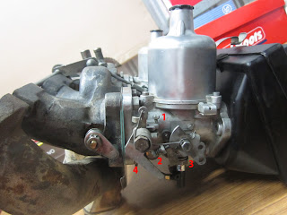
Tuning the SU-HS6 carbs Volvo Amazon B20B engine
Tuning the SU-HS6 carbs

  • Turn the throttle stop screws (1) out until they just lightly touch the levers and then turn them in 1.5 turn.To check when the screws start to touch the levers I always put a piece of paper between the screw en lever. Keep moving the paper until you feel resistance, now that's the correct point
  • Screw in the jets (3) until they are flush with the bridge, (the jet just touches the air valve). I checked this first just by looking and if it looks OK by lifting the air valve and let it fall while holding my finger at the bottom of the black plastic part. This way you can feel if the air valve hits the jet or not. Then it's a matter of fine tuning 
Jet flush with bridge SU-HS6 carburettor
  • Now screw out the jets 15 hex flats (2.5 turns) -I put a dot with a marker on the hex flat in front when the jet just touches the air valve, which helps while counting. You'll see that you probably have to adjust the jets a couple of times before you get them right.
  • Fill the damping cylinders with special ATF oil (type A), 6- 6,5 mm from the top.
Now you can start the engine and do some more fine tuning.

Always start with the ignition and valves before tuning the carburetors.

Setting the Dwell Angle
When the engine is running you can measure the Dwell Angle, this is a more accurate way of measuring the gap between the breaker points which should be 0.4 - 0.5 mm. The Dwell Angle for the B20B engine should be between 59 - 65 degrees. To measure the Dwell Angle, advance timing settings and the RPM you need a special multi meter (see pic).

Optilux Timing/dwell/rpm multi meter

Because I always like to know why I have to tune something and how it works first some theory about setting the dwell angle: The distributor shaft has to ignite four sparks in one turn (360 degrees). So we have 90 degrees for each spark. The spark is made by the ignition coil. This coil needs a certain amount of time to build up the power for the spark. This is only possible when the breaker points are closed. A dwell angle of, let's say 60 degrees means that the breaker point should be closed 60/90 part of the time to build up enough power for a strong spark. The bigger the contact breaker gap the lower the dwell angle!! If the dwell angle is to high, the breaker points will wear and get pitted very fast. If the dwell angle is to low the spark can get to weak, especially when revving the engine.

Bosch Distributor JFUR 4 -  Volvo 122S B20B

Next thing to tune is the ignition timing.
In order to get max power on the pistons you need max pressure of the explosion when the Piston is in TDC (Top Dead Centre), but because the fuel/air mixture need a certain time to burn and thus generate max pressure it has to be light (sparked) before the piston is in TDC. So we need to advance the ignition.
There are several things that contribute to the advance settings:

- Initial (base) Advance Timing
On the pulley you can see marks (the same pulley we used for setting the valve clearances) and when the engine is running at idle speed (Volvo B20B around 800 rpm) you can look at it with the stroboscope light and read the timing.Disconnect the vacuum hose and plug the hole before you start.  In order to change the timing loosen the bolt that holds the distributor a bit and carefully turn the distributor while the engine is running at 800 rpm. Turn to the left will increase the advance, turn to the right will decrease the advance setting. For the Volvo B20B the base advance should be 10 degrees.

- Mechanical (Centrifugal) Advance Timing
When increasing engine speed (rpm) it needs more advance timing to keep up with the piston speed because the time the burning gasses need to reach optimum pressure to push the piston down when it is in TDC stays almost the same. The mechanical timing advance is caused by a mechanism inside the distributor. The distributor in the Volvo B20B has a total (max) mechanical advance of 13.5 degrees (+/- 1 degree). And because the distributor turns half the speed of the crankshaft you have to multiply it by 2 to calculate the real advance.
It's important to know that the Total Advance Timing (Initial + 2x Mechanical) has a max of around 38 degrees. If you set it higher the engine can start to pink (gas detonates too early caused by high pressure/heat) which can cause severe damage! It's a "metallic pinging" sound.

- Vacuum Advance Timing
A lean mixture needs more time burn. So when the engine is idling or your driving at a constant speed on the highway the engine needs a bit more advance then normal. This is when the vacuum advance kicks in. Vacuum in the carburettors is at it's highest point when idling or travelling at a constant speed with low rpm.
Normally, yes... But the Volvo B20B engine has a distributor with a vacuum system that retards the timing.. I still have to find out why and how.

Specifications Bosch JFUR 4 Distributor - Volvo Amazon B20B
Specifications Bosch JFUR 4 Distributor

Keep in mind that the specifications given by Volvo are based on an original/unmodified engine and when the fuel used to be 100 oct or more. When the octane in the fuel is lower you need  a lower initial advance timing. I think around 8 with 95. But.. because my engine has a sporty K-camshaft it needs an higher degree of advange than normal (because the valves open earlier than normal). I couldn't find the corresponding Settings for the K-camshaft but for now I'll set it around 12 degrees. If you want maximum power from your engine set it as close to pinking as possible. So when I take it for a ride when it's finished and it's not pinking maybe I'll give it 1 or 2 degrees more Advance timing..


Fine tuning the SU-HS6 carbs.
I did the settings without a CO-meter. According to the manuals Temperature is an important factor when making the settings; 
- Ideally the outside/shed temp should be between 15-25C
- The settings should be made within 1-3 minutes after the thermostat has opened!

So start the engine and run it warm at around 1500 rpm until the thermostat opens (the top hose suddenly becomes warm) and then adjust the  throttle stop screws (1) until the engine speed is 800 rpm. Turn both screws equally!!
Now turn the jet nut (3) of the rear carburetor until max idling speed is obtained and then turn them inwards (leaner mixture) until the rpm starts to drop. This is the right setting. To check this, push the lifting pin, the rpm should drop 150-250 rpm. I had to turn the jet adjusting screws almost 3 hex inwards counted from the "zero"setting to get the setting right.
Re-adjust the idling speed with the throttle stop screws to 800 rpm.

I had a couple of "problems" before the B20B was tuned. First problem was flooding caused by a wrong float level (ca.4.6 mm) at one of the floats. I adjusted both float levels to approximately 5.2 mm, because I didn't want any more fuel from the float chambers leaking on the hot exhaust ("better safe than sorry"). The flooding stopped.. but so did the engine after a minute or 2. Hmm, what's wrong this time.. I checked the float chambers and they were almost empty!! Apparently there are really narrow margins around the 4.8 mm float level.

almost empty float chambers SU carbs Volvo B20B caused by a wrong float level
Almost empty float chambers caused by a wrong float level

The next issue was a uneven idling. Normally this is caused by a vacuum leak. Well I found two.. The old hose from the brake booster was ripped (hard to see because it was the underside) and the other one was the preheating chamber in the inlet manifold caused by 2 "loose" bolts (see pic above).

Ripped vacuum hose from inlet manifold to the Ate brake booster Volvo B20B
Ripped vacuum hose from inlet manifold to the Ate brake booster
I also need a new air filter because the old one is so dirty it almost suffocates the engine.

Update 05-04-2014: check for more tuning also http://volvo-122s.blogspot.com.au/2014/03/volvo-122s-b20b-engine-more-tuning.html

O.... and the felt seals luckily stopped leaking after a while,  All good


Volvo B20B engine after some tuning