Aug 29, 2012

Fitting the pistons back in the block

Now the crankshaft was finally back in the block it was time to fit the pistons back in the cylinders. Just carefully put the piston rod in the cylinder, squeeze the piston rings and push the piston back in the cylinder bore.
I've done that a dozen times with bike engines (mainly Honda's and a couple of Kawa's) but this time something went wrong. While putting the pistons and rings back in the cylinders with a piston ring compressor I got a phone call. After that I just tried to push the piston back in the bore. But in the meantime the middle piston ring got out of the claws of the compressor and when I pushed the piston ... it broke..(of course stupid...).

Broken piston ring Volvo 122s 0.030"
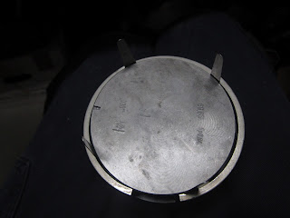
Today the new piston ring came in the mail :). I only needed to fit the second one, so first I took out the top ring. I used an old trick to fit the piston rings; take 4 feeler gauge blades and fit them with a rubber band around the piston. Then slide the ring over blades on the piston.

Fitting piston rings with an old trick - using feeler gauge blades
Fitting piston rings with an old trick -
using feeler gauge blades and a rubber band

Fitting piston rings with an old trick - using feeler gauge blades and a rubber band
Fitting piston ring using feeler gauge blades
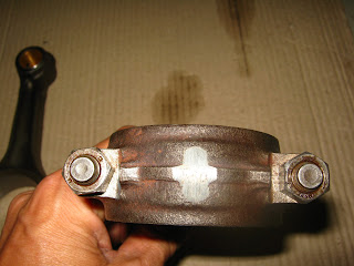
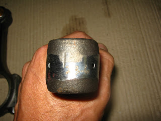
Now it was time to fit the shell bearings to the rod and cap and put the pistons back in the engine. I used assembly lube on the shell bearings before connecting them to the crankshaft and cleaned the bearings with alcohol to remove all the protective grease. Don't use lube between the shell bearing and rod!

Piston rod Volvo B20 with new bearing
Piston rod and cap with new shell bearings
Tighten the bolts of the piston rods to a torque of 45 Newton-meter
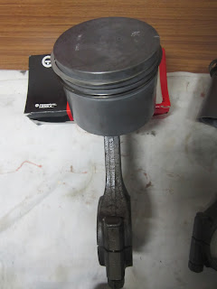
Pistons back in engine Volvo 122S B20B
3 of 4 Pistons back in engine Volvo 122S B20B
Whe all the pistons were back in the cylinders I tested if everything was alright by turning the crankshaft. All good and smooth.

Testing the crankshaft and pistons after reassembling


Aug 27, 2012

Rebuilding the SU HS6 Carburetters


The double SU HS6 carburetters were covered in a mix of grease, oil and mud. As I bought the car with the engine in bits I didn't know in what condition they were and decided to clean them thoroughly, dismantle them and do some rebuilding.

SU HS6 carburetters AUD331 Volvo B20B
SU HS6 carburetters AUD331 after 13 years collecting dust
The rebuild kit you need for these SU HS6 carburetters is CRK 249. This kit doesn't come with the jet needles as they vary depending on the engine and carburetter number. The labels on the carbs indicated AUD331, so according to a needle chart I needed spring-loaded needles with code AUD1538 KN.

Rebuild kit for SU HS6 carburetters
Rebuild kit CRK 249 for SU HS6 carburetters

Needle chart SU carburettors Volvo B14 B16 B18 B20
Needle chart SU carburetters Volvo B14 B16 B18 B20
The rebuild kit came with new throttle flaps and shafts. To use them you need to ream out the old bushings and then press in the new ones which is something for a specialist. The reason to replace them is that false air can be sucked in through the space created between the shaft and the bushings after many years. I decided not to replace them to save some money. If leaking, the carbs can be easily removed to bring them to the shop for the in line reaming.
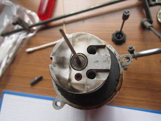
After cleaning the outside of the carbs with turps and alcohol I disassembled the first one and made pics of every step so I had some reference material when rebuilding. I think it's been the first time the inside of the carbs saw daylight in 43 years. I discovered that the needle in the second carb wasn't fit correctly.The mark/line on the needle guide should point away from the ports in the piston/air valve, so the needle leaned in the wrong direction which caused severe wear in the jet and on the needle itself.

Air valve SU HS6 carburetter Volvo B20B
Dirty Air valve SU HS6 carburetter

Air valve SU HS6 carburetter with spring-loaded needle
Air valve SU HS6 carburetter with spring-loaded needle,
note that the needle isn't installed correctly

Air valve with guide, spring and KN needle SU HS6 carburetter
Air valve with guide, spring and KN needle 

Dirty inside of the SU HS6 carburettor
Inside the SU HS6 carburettor

Old jet with needle SU HS6 carburetter
Old jet with KN needle SU HS6 carburetter,
see how the jet feed pipe fell in bits when disassembling

Replacing the spring-loaded needle and jet is pretty straight forward and will take only 15 minutes or so.
When replacing the needle make sure the needle guide is flush with the piston and that the mark on the guide points away from the ports in the piston. The jet assembly is hold by one screw and one bolt which connect the float chamber with the feed pipe. 
With most SU carburetters you need to centre the jet after replacing the needle and/or jet. But with this one it's not possible and thus not neccessary.

Spring-loaded KN needle and jet in SU HS6 AUD331 carburettor
Spring-loaded KN needle and jet close up

I also replaced the needle valve and seat in the float chamber and checked the float level (ca. 4.8 mm). 
Another thing to check is the damper piston clearance. Don't be fooled by the Haynes manual, the right clearance for the AUD331 carbs should be 0.4-0.8 mm.

float chamber SU HS6 carburettor disassembled

Old and new needle float chamber SU HS6 carburettor
Old (left) and new needle float chamber 

Messuring the float level SU HS6 carburetter

Messuring the damper piston clearance SU HS6 AUD331 carburetter
Messuring the damper piston clearance (0.4-0.8 mm)
 SU HS6 AUD331 carburetter

After reassembling the carbs they need tuning. But in order to tune them you need a running engine... Hmmm.. back in the box for now.

Rebuild SU HS6 AUD331 carburetters

Rebuild SU HS6 AUD331 carburetters
Rebuild SU HS6 AUD331 carburetters, they only need some tuning

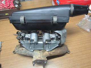
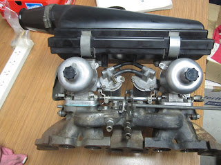
SU HS6 carburetters mounted on manifold Volvo 122s B20B
Carburetters mounted on manifold 

SU HS6 carburetters mounted on manifold Volvo 122s B20B
Carburetters mounted on inlet/outlet manifold 

SU HS6 carburetters mounted on manifold Volvo 122s B20B

SU HS6 carburetters mounted on manifold Volvo 122s B20B


Aug 26, 2012

Assembling the engine Volvo B20B - Crankshaft

Because the crankshaft was grinded it needed new undersize bearings. 0.010" (0.254 mm).
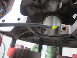
Before I replaced the crankshaft I cleaned and then checked all the oilways; cleaning with compressed air and checking by simply injecting some oil in each oilway and see were it goes. The engine block was upside down on the engine stand when doing this.

Volvo 122S crankshaft new undersize bearings. 0.010" (0.254 mm)

Volvo 122S crankshaft new undersize bearing. 0.010" (0.254 mm)
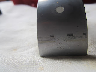
Mark/undersize number on Glyco shell bearing

Volvo 122S crankshaft new undersize pilot shell bearing. 0.010" (0.254 mm)
Mark/undersize number on Glyco shell pilot bearing

Checking the oilways Volvo B20B by injecting some oil

Checking the oilways Volvo B20B see were the injected oil goes

Checking the oilways Volvo B20B crankshaft seatinjected oil goes to camshaft bearing
Volvo B20B crankshaft seat injected oil goes to camshaft bearing
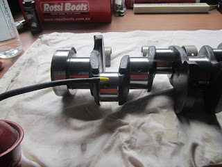
Oilways Volvo B20B crankshaft
Checking and filling the oilways Volvo122S  B20B crankshaft
Filling the oilways Volvo B20B crankshaft
After checking the oilways I wiped the seats clean and removed all the protective grease from the bearing shells. Then I placed the shells on the seats and put some assembly lube on them. Now I could place the grinded crankshaft on top of them.  But the pilot (no. 5) shell bearing was to big/wide for the grinded crankshaft......%$$#N$. I brought it back to the shop together with the new undersize bearings so they could grind the sides of the crankshaft. Btw: Never shave the shell bearing to make it fit!

pilot shell bearing Volvo 122s B20B
Pilot shell bearing Volvo 122s B20B doesn't fit


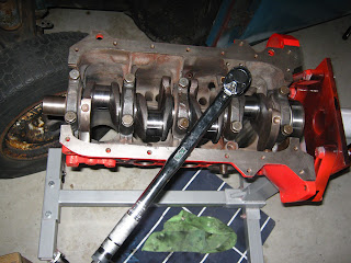
A couple of days later I could finally tighten the nuts with the torque wrench (122 N/m)

Next step is fitting the pistons.


Aug 13, 2012

Assembling the engine Volvo B20B - Pistons

When I bought the car it came with new Mahle pistons (0.030") and luckily the new piston rings were already fitted. The pistons were also assembled to the rusty connecting rods. In order to clean and balance the rods I took the pistons off again. The rods were then balanced together with the crankshaft and flywheel. This was 2 months ago..

New Volvo 122S B20B Mahle piston 0.030" with rusty rod

Balanced connecting rod - cap

Balanced connecting rod - top

Easy...not! It was somehow really hard to get the gudgeon out of the pistons again and the rod cap bolts were impossible. But after some @#$%#@**!% and WD40 I managed to take it in bits :-).

Gudgeons out , bolts still tight which I didn't realised when taking the picture
I thought everything was ready for the assembling...

When assembling the pistons to the rods with the gudgeon pins it very important to do it the right way.


  • On top of the piston you can see a mark; this mark should face to the front of the engine
  • On top of the pistons there's also a number (1, 2, 3 or 4); this number should correspondent with the cylinder bore number. Number 1 is the cylinder bore at the front of the engine
  • On the rods and their caps you can find the same numbers for the same purpose
  • When connecting the rod with the piston make sure the rod marking numbers face away from the camshaft side when installed in the engine.

On top of the piston you can see a mark this should face to the front of the engine
You can also see a number (no. 2 for this one)

Numbers/marks on the rods and the rod caps

When connecting the rod with the piston make sure the rod marking numbers face away from the camshaft side when installed in the engine
Thre right way to connect the rod to the piston, see the marks/numbers on both

Pistons assembled to the rods with the gudgeon pins

Some Maths
I was curious what the new engine capacity should be with the 0.030" Mahle pistons.
The formula to calculate the capacity of an engine:

Capacity (in cc)  =  (π/4 x bore² x stroke x # cylinders)/1000   (note: π ≈ 3.14)
Original engine: (3.14/4 x 88.9² x 80.0 x 4)/1000    1986 cc
Rebuild engine with 0.030" (0.762 mm) Mahle pistons:
 (3.14/4 x 89.66² x 80.0 x 4)/1000    2020 cc
An increase of 34 cc !


Assembling the engine Volvo B20B - Cylinder head

This weekend I started assembling the Volvo B20B engine.
First thing to do was replacing the valves in the cylinder head.
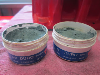
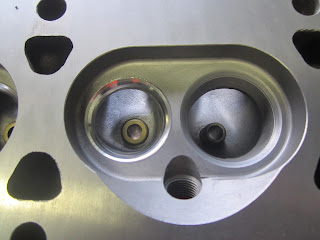
Altough the inlet valve seats were vacuum tested I decided to give them a light grind so the valve and the seat would have exactly the same slope. I didn't grind the new outlet valve seats because they were already cut in the same slope as the outlet valves in the shop.
Grinding paste - coarse and fine

Grinding paste on inlet valve seat Volvo 122S B20B
Grinding paste on inlet valve seat 

Grinding inlet valve seat Volvo 122S B20B
Grinding inlet valve seat 

Grinded valve seat Volvo 122S B20B
Grinded valve seat Volvo 122S B20B - see the matt grey ring
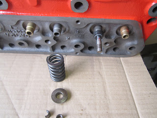
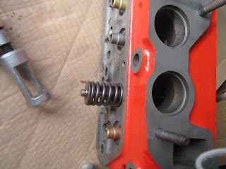
After grinding I cleaned the head thoroughly with air. Then the valves and springs were replaced in the cylinder head. I used assembly lube to lubricate the valve stems. Because this oil has a high viscosity I also used it on the tiny collets to "glue" them to the valve stem while releasing the valve compressor.

Ready to place the valves in the Volvo B20B head

New rubber sealing ring placed over valve guide

Valve spring compressed and collets glued to valve stem with lube
Valve spring compressed and collets "glued" to valve stem with lube

First valve done
First valve done